2. Hebei Yanxing Machinery Co., Ltd., Zhangjiakou 075000, China
2. 河北燕兴机械有限公司, 河北 张家口075000
With the proposed emission peaks and carbon neutrality goals, renewable energy power generation driven water cracking hydrogen production technology is developing at an unprecedented speed. On the one hand, it can reduce the waste of wind power and photovoltaic energy, thereby promoting the maximum utilization of wind and solar energy; On the other hand, as an efficient and environmentally friendly technology, it is very suitable for the goal of sustainable development. However, the slow oxygen evolution reaction (OER) in electrolytic water severely limits the large-scale application of this technology. Therefore, more and more electrocatalysts have been studied to accelerate OER.
Among the non-noble metal electrocatalysts developed for OER, NiFe based materials have attracted considerable attention due to their abundant reserves and excellent performance under alkaline conditions. As early as the last century, Corrigan[1–2] conducted a series of studies on iron doped nickel hydroxide, and other research groups further studied [3−6]. The results showed that appropriate iron doping can improve the valence of nickel and form more active sites. It is well known that NiFe oxyhydroxide has excellent activity for OER. Fan[7] synthesized NiFeOOH with abundant oxygen vacancies (Ov). The results showed that the shortened Fe―O bonds and oxygen defects of NiFeOOH synergistically improved the interaction between the metal cations and intermediate species, which was beneficial to accelerating the entire reaction kinetics. A three-dimensional integrated anode electrode was prepared by electrodeposition of NiFeOOH on a gas diffusion layer instead of conventional electrode, which has stable activity over 500 h[8]. In addition, comparing the reported literatures[9−17], it can also be found that different nanostructured materials have different catalytic properties. Rong et al.[18] reported a series of NiFeOOH materials for OER. When the Ni/Fe molar ratio is 7, the morphology of NiFeOOH remains nanoflakes, but when the Ni/Fe molar ratio is further reduced, it transfers from nanoflakes to bulk particles. Accordingly, their performance varies. Due to their unique two-dimensional (2D) structure, nanosheets have a large plane size while maintaining atomic thickness, so they have a large specific surface area; and the high exposure of surface atoms provides conditions for easy control of material properties through surface modification/ functionalization, elemental doping or defects, strain, phase engineering, etc[19]. Therefore, it is of great significance to prepare NiFeOOH catalyst with nanosheet morphology. Up to now, the conventional methods for preparing these catalysts mainly include hydrothermal/solvothermal, co-precipitation and electrolytic deposition. However, all of these methods require additional device and energy supplementation, which are costly and run counter to green energy. So it is necessary to develop new cost-effective strategies to synthesize efficient nickel-iron-based materials. In addition, transition metal-based electro- catalysts are usually combined with polymer binders such as Nafion as electrodes, resulting in poor electrical conductivity and mechanical stability. A feasible solution is to directly grow active electrocatalysts on conductive substrates such as nickel foam electrode plates.
From a chemical perspective, corrosion products often form compounds of metal (hydro) oxides and may contain sulfides or chlorides, which can be used as a general method for producing unconventional nanostructures[20]. Inspired by the above discussion, a new OER electrocatalyst was synthesized in this work. NiFeOOH nanosheets were grown on the surface of NF by controlling the corrosion conditions. Interestingly, the synergistic effect of Ni and Fe is significantly beneficial to the formation of -OOH. At the same time, as a conductive substrate, NF can not only obtain a three-dimensional structure with large surface area, but also simplify the preparation process without adding additional Ni, Fe element.
1 Experimental 1.1 Preparation of catalystsNF with different Fe content was prepared according to our previous report[21]. NiFe alloy was electrodeposited on the treated polyurethane sponge by constant current electrolysis. The ratio of Ni to Fe in the NiFe alloy can be adjusted according to the mass changes of FeSO4·7H2O and NiSO4·6H2O. After 1~2 h of plating, a shiny metallic porous NiFe alloy was obtained. Piranha solution (PS) is a mixture of sulfuric acid (H2SO4, 95%~98%, Tianjin Chemical Regent) and hydrogen peroxide (H2O2, 30%(Mass fraction) in H2O, Tianjin Chemical Regent) (3∶1 by volume ratio) and left to cool completely. NF was soaked in the PS at a controlled temperature for different periods of time, then taken it out and cleaned by deionized water and ethanol for three times, respectively. Finally, the sample was dried in a vacuum drying oven at 40 ℃, marked as NiFe-PS. Additionally, the samples prepared by varying only the reaction medium(H2SO4 or H2O2) were labeled as NiFe-H2SO4 and NiFe-H2O2 under otherwise identical conditions.
1.2 Catalyst characterizationX-ray powder diffraction (XRD) was performed using a Rigaku Smartlab SE X-ray diffractometer with Cu Kα radiation (λ = 0.154 18 nm) at a scanning rate of 2(°)·min−1 in the 2θ range of 5°~80°. The morphology and elemental mapping of the prepared samples were observed by scanning electron microscopy (SEM) (TESCAN MAIA 3 LMH) coupled with elemental Mapping. The compositions of the as-prepared samples were analyzed by inductively coupled plasma analysis (ICP Varrian 720). The elemental valences were analyzed by X-ray photoelectron spectroscopy (XPS) with a ESCALAB 250xi using a monochromatic Al Kα X-ray beam (1486.6 eV).
1.3 Electrochemical measurmentsThe catalytic performance was measured on a CHI760E electrochemical workstation (CH Instruments, Inc., Shanghai) in a standard three-electrode system, the Self-supported catalyst (0.5 cm × 0.5 cm) as working electrode, a Pt foil electrode (1.0 cm ×1.5 cm) and an Ag/AgCl electrode were served as the counter and reference electrode, respectively. In all analysis, the Ag/AgCl reference electrode was calibrated with respect to reversible hydrogen electrode (RHE) according to E(RHE) = E(Ag/AgCl) + 0.204 + 0.059 pH in 1.0 mol∙L−1 KOH. The overpotential (η) was calculated by E(RHE) −1.23 V. Linear sweep voltammetry (LSV) measurements were conducted in the electrolyte at scan rate of 5 mV∙s−1 (scanning range from 0 to 1.5 V). Chronopotential curve was recorded to evaluate the lifetime of electrocatalyst for OER. Electrochemical impedance spectroscopy (EIS) measurements were performed on Zahner electrochemical workstation (Cimps-2, Germany) by applying an AC voltage of 10 mV amplitude in a frequency range from 0.01 Hz to 100 kHz at 1.623 V.
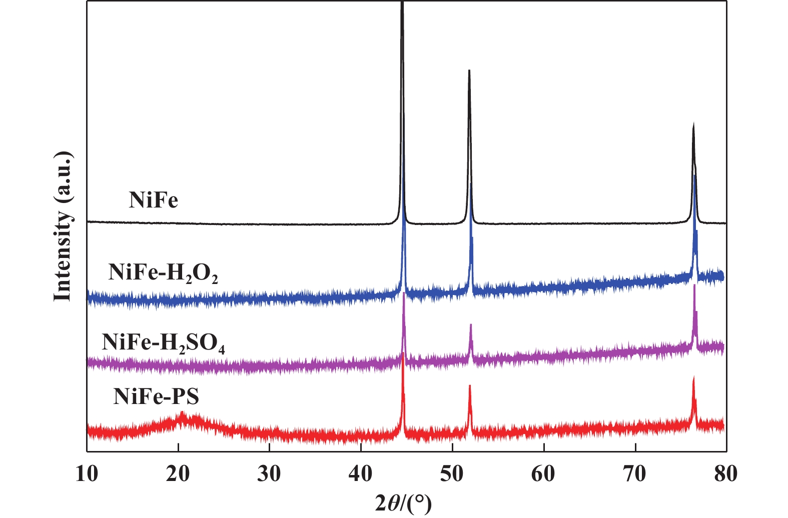
2 Results and discussionThe XRD patterns of the samples are shown in Fig. 1. NF shows three obvious and sharp peaks, which are well matched with the phase of Ni3Fe alloy (PDF 38-0419). For NiFe-PS, it can be clearly observed that there is also an obviously wide peak at around 21°, which may be assigned to the NiFeOOH[22–23] besides the corresponding peak of NF. However, the intensity of NiFeOOH is very weak, possibly due to the poor crystallinity of NiFe alloy covered with a very thin catalyst film. In addition, there are two tiny peaks at 21.7° and 31.1° respectively, indicating the presence of S[24]. Interestingly, these other peaks were not observed in the samples treated with H2O2 or H2SO4 alone, suggesting that the catalytic performance of samples may differ under different oxidation conditions.
|
Fig.1 The XRD patterns of catalysts at different oxidation conditions |
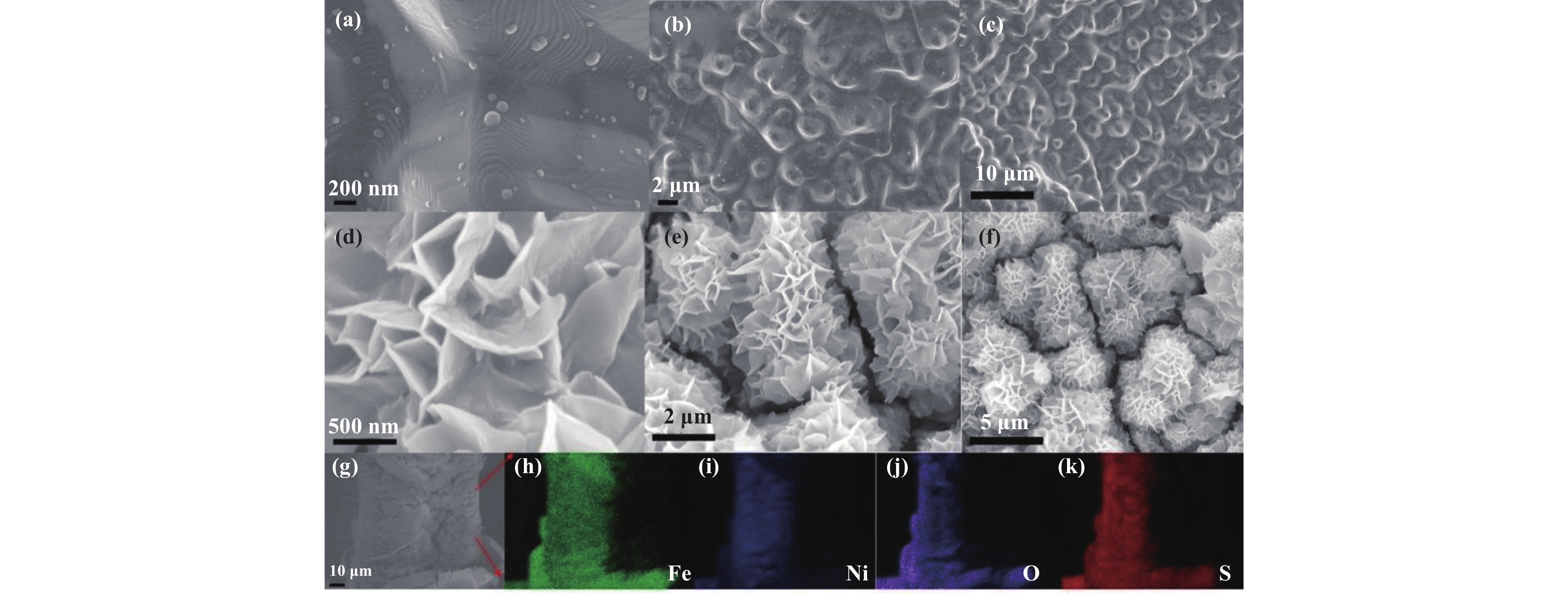
The morphology of 10%NiFe alloy before and after oxidation was analyzed by SEM, as shown in Fig. 2. The surface of the sample has undergone significant changes. Significant surface changes can be observed after oxidation of the sample. Comparing Fig. 2 ((a), (b), (c)) and Fig. 2 ((d), (e), (f)), it was found that the surface of the unoxidized NiFe alloy was relatively smooth and clean. After oxidation, the surface became significantly rougher, and nanosheet morphology was grown, with a thickness of about 25 nm. In addition, as shown in Fig. 2(f), at low magnification, the nanosheets generated on the surface have a nearly spherical structure, forming an interconnected network structure with open pores overall, which is similar to the morphology of NiFeOOH prepared by hydrothermal method in references[24–25]. This structure may provide a larger accessible area of electrolyte and more mass/ion diffusion pathways, therefore promote OER kinetics to obtain better activity. Fig. 2((g)–(k)) shows the elemental spectrum of NiFeOOH/NF, identifying four elements, namely Ni, Fe, S, and O. Among these elements, the distribution of O element is significantly expanded compared to NiFe alloy, indicating that the surface of NF is oxidized. The uniform distribution of S not only indicates that the piranha solution did indeed oxidize the NiFe alloy during the preparation process, but also suggests that the OER performance of the catalyst may be affected by S element.
|
Fig.2 The SEM images of 10%NiFe alloy foam before ((a), (b), (c)) and after ((d), (e), (f)) oxidation and mapping ((g)–(k)) |
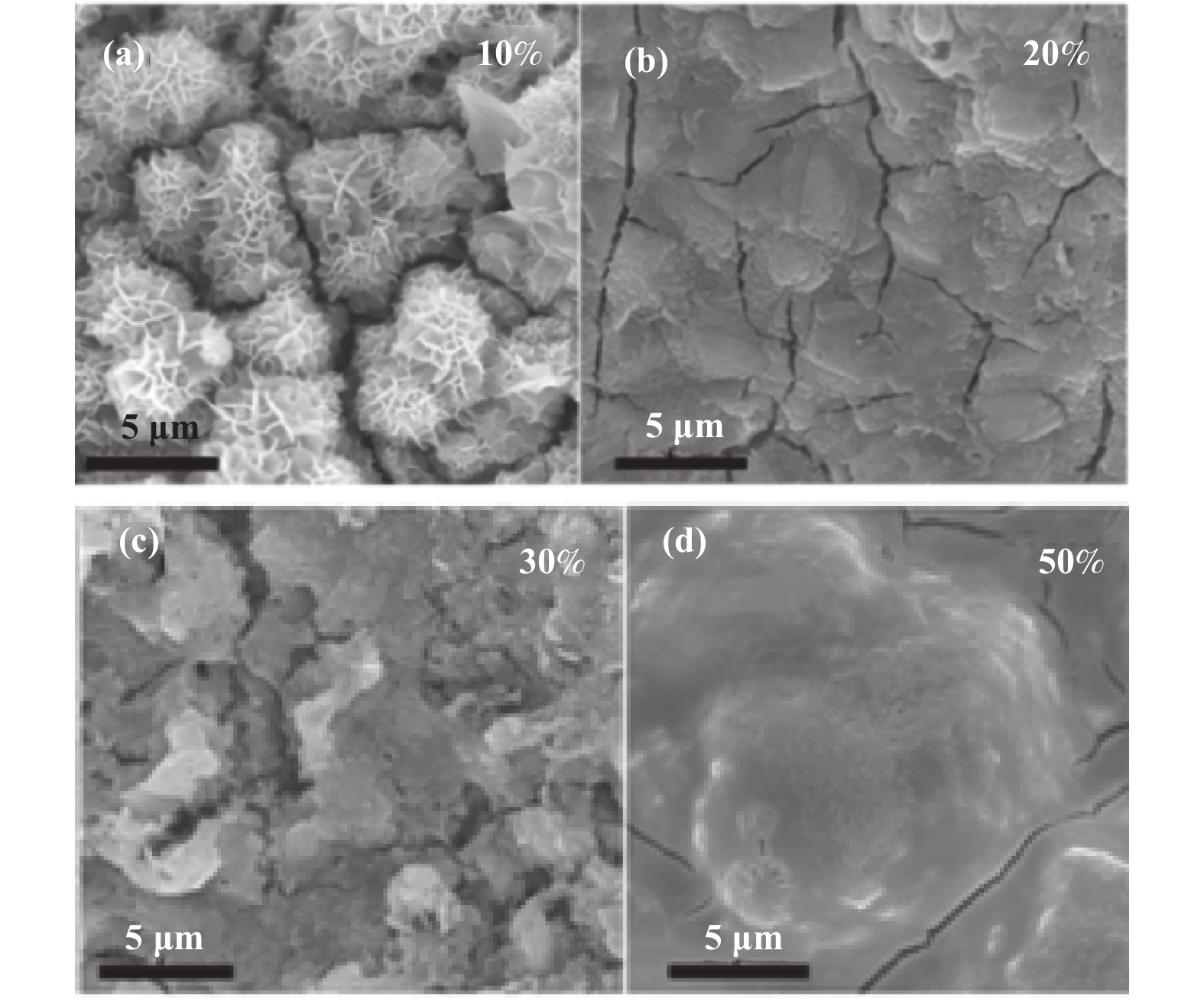
Also, as shown in Fig. 3, the morphology of foamed NiFe alloys with different Fe contents (10%, 20%, 30% and 50%) after oxidation was further characterized by SEM. In contrast, NF with Fe content of 10% presented with the shape of nanosheets after oxidation, while other samples with different Fe content only become rougher, forming irregular and large-sized agglomerations, which differed significantly from the morphology of 10%NiFe-PS. The results indicate that the OER performance of oxidized samples with different iron contents may vary. Inductively coupled plasma (ICP) analysis was used to confirm the component contents in the as-prepared NF with different Fe contents. The Fe and Ni contents by weigh in NF samples with different Fe contents (10%, 20%, 30% and 50%) are 9.12%, 88.90%; 17.47%, 80.94%; 28.08%, 69.42% and 48.55%, 50.38%, respectively.
|
Fig.3 The SEM images of NiFeOOH/NF with different Fe contents(10%(a), 20%(b), 30%(c), 50%(d)) |
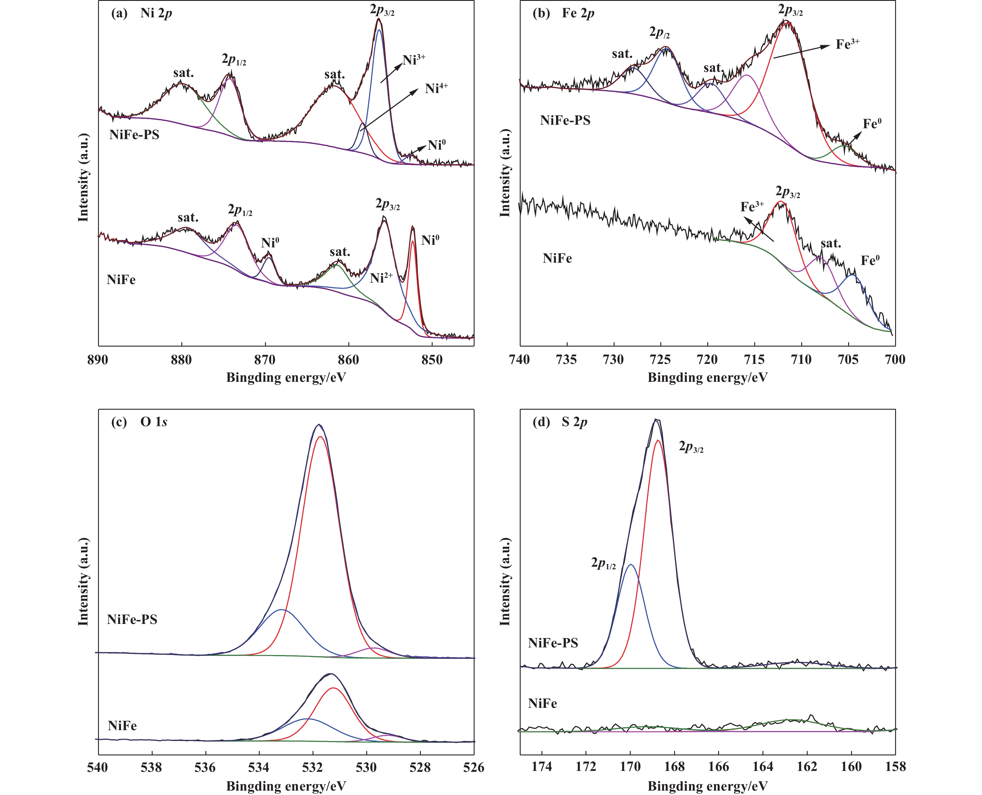
In order to further determine the composition and valence states of the catalyst by XPS test. The Fig. 4(a) shows the high-resolution XPS of Ni 2p of the samples. For NF, there are four obvious spin-orbit peaks of Ni 2p3/2 and 2p1/2 at 852.36/855.65 and 869.54/873.45 eV, respectively, the former two peaks can be unambiguously identified as the metallic Ni and the latter two can be assigned to the Ni2+, the other peaks with the binding energies at 861.35 and 879.13 eV are the corresponding satellite peaks, this is typical peak of Ni2+[26]. Furthermore, according to the pertinent literatures, the binding energy difference is 17.8 eV between the 2p1/2 and 2p3/2, suggesting that the existence of Ni(OH)2 in the catalyst[27], by contrast, for NiFe-PS, metallic Ni peak intensity decreases drastically, the shift to slightly higher binding energy (~0.7 eV) means that a change in the electronic structure occurs upon the phase conversion. Therefore, the peaks of 856.35 and 874.25 eV are assigned to Ni3+[28−30]. Significantly, there is a new weak peak at 858.31 eV which can be ascribed to Ni4+[31]. The Fe 2p is shown in Fig. 4(b), for the NiFe-PS, the peaks of 711.35 and 724.28 eV are assigned to 2p3/2 and 2p1/2 of Fe3+[27], the peak of 705.48 eV belong to metallic Fe[31], and the former is stronger than NF, while the latter is lower than it, indicating that PS accelerated the oxidation of Fe. The O 1s spectrum is shown in Fig. 4(c), it exhibits three peaks located at 529.73, 531.73 and 533.22 eV, which are successively ascribed to the M—O bonds, M—OH bonds and absorbed H2O[27, 31]. Compared with NF, the peak intensity of M—OH is stronger, indicating the content of NiFeOOH is higher, and in NF, the peak of 529.22 eV is ascribed to Ni—O bonds, indicating that PS tend to promote the formation of M—OH bonds and Fe—O bonds. All the above results demonstrate that PS accelerates the oxidization of NF and the formation of NiFeOOH. In the S 2p spectrum (Fig. 4(d)), the presence of S is completely negligible in NF, while for the NiFe-PS, there are obvious two peaks located in 168.7 and 169.98 eV, which correspond to residual sulfate groups or oxidized sulfur species due to surface oxidation[32], the results show that the surface of the oxidized catalyst contains S element that can reduce the adsorption free energy of OH* and the free energy between O* and OH*[33], thereby improving OER performance.
|
Fig.4 XPS spectra of NiFe-PS and NiFe : Ni 2p(a); Fe 2p(b); O 1s(c); S 2p(d) |
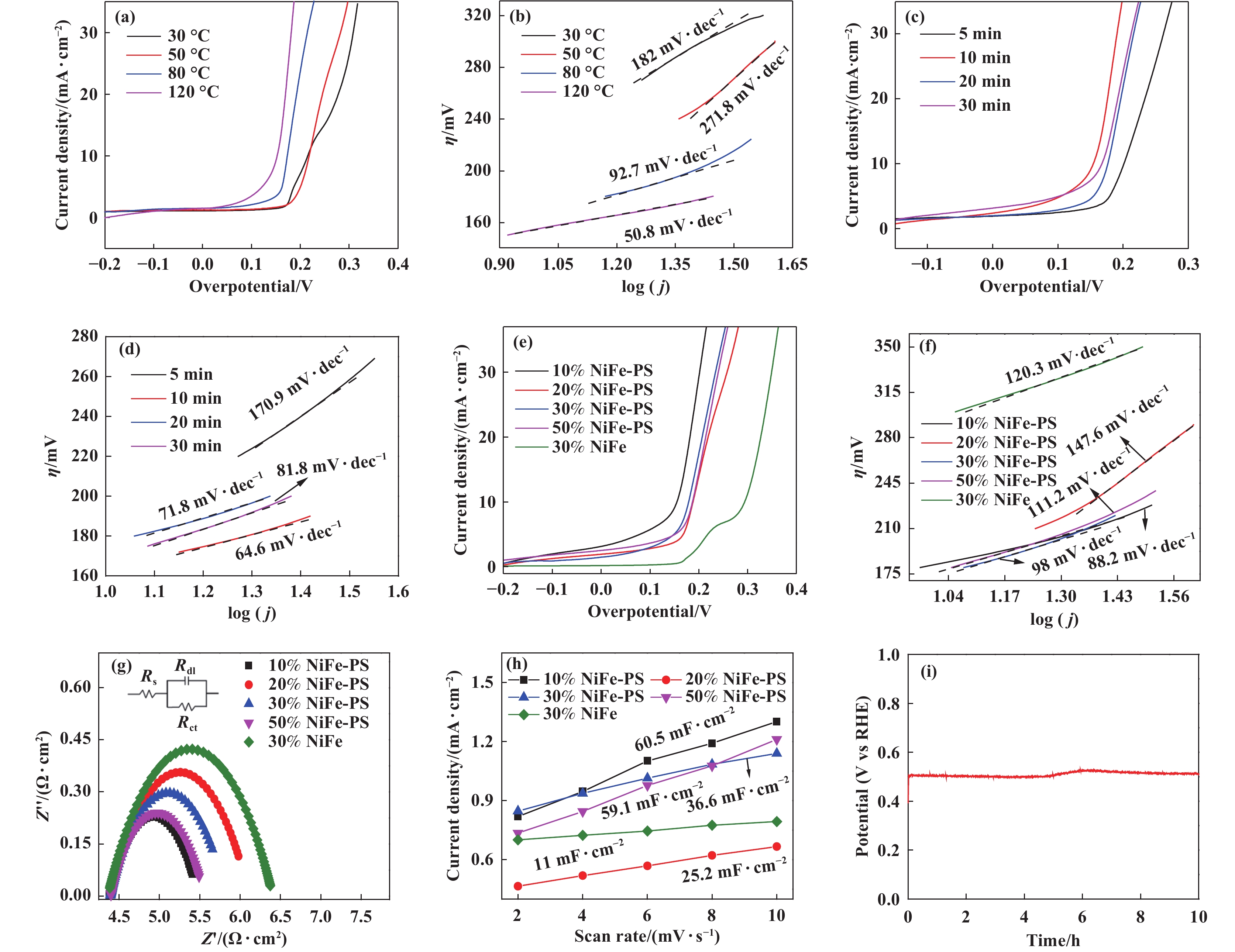
The electrochemical performance of NF at different oxidation condition was tested. As is shown in Fig. 5((a), (b)), the overpotentials of NiFeOOH/NF at 30 , 50, 80 and 120 ℃ were 215.11, 217.87, 174.26 and 155.68 mV at 10 mA∙cm−2, respectively, the Tafel slopes were 182, 271.8, 92.7 and 50.8 mV∙dec−1, respectively, which were consistent with the overpotential results. When the oxidation at higher temperature than 120 ℃, it is found that the NF very quickly dissolved in PS solution. Therefore, the sample prepared at 120 ℃ has the lowest overpotential and Tafel slope, showing reaction kinetics of the catalyst is the fastest, indicating that the oxidation of the catalyst would be promoted with increasing of the temperature, so catalytic performance is increased. Then, the influence of different oxidation time on samples was studied, as shown in Fig. 5((c), (d)). At 10 mA∙cm−2, the overpotentials of samples were 201.53, 155.68, 176.85 and 167.09 mV at 5, 10, 20 and 30 min, respectively, and their Tafel slopes were 170.9, 64.6, 71.8 and 81.8 mV∙dec−1, respectively. The results of overpotential and Tafel slope show that the overpotential increases firstly and then decreases with the increase of oxidation time, which may be attributed the number of Ni3+/Ni4+ and Fe3+ on the surface of samples were increased with the increase of oxidation time. Surface formation of α-FeOOH may block the active site of NiFe hydroxyl oxide if the oxidation time for too long, thereby reducing its availability[34].
|
Fig.5 The LSV curves ((a), (c), (e)) and Tafel curves ((b), (d), (f)) of NiFe-PS with different oxidation temperature, time and Fe content, EIS(g), linear fitting curves of the current density versus CVs scan rates (h) of NF before and after oxidation of PS and Chronopotential curve curve of NiFeOOH/NF(i) |
The influence of catalysts with different Fe content on OER performance was investigated. Fig. 5(e) showed the LSV curves of different samples. Compared with NF with 30% Fe content, other samples oxidized by PS showed no oxidation peak between 0.2~0.3 V. Combined with XPS analysis, it was speculated that this might be due to the strong oxidation of PS, so the state of Ni was directly oxidized to +3 during the preparation process. The overpotentials of 10%NiFe-PS, 20%NiFe-PS, 30%NiFe-PS and 50%NiFe-PS were 155.68, 189.14, 179.24 and 186.39 mV at 10 mA∙cm−2, respectively. As can be seen from Fig. 5(a), the overpotentials of NiFe-PS are significantly lower than that of NF (293.74 mV). Among NiFe-PSs with different Fe content, 10%NiFe-PS has the smallest overpotential. Further analysis was conducted on the Tafel slope of the sample. As shown in Fig. 5(f), the values were 88.2, 147.6, 98, 111.2 and 120.3 mV∙dec−1, respectively. The Tafel slope of the other samples was lower than that of the untreated samples except for 20%NiFe-PS, and the Tafel slope of 10%NiFe-PS is the lowest. The results showed that the OER performance and reaction kinetics of 10%NiFe-PS were excellent, and the OER performance of the catalyst was affected by the content of Fe element, suggesting that in addition to Ni, Fe may also be the catalytic active site in the reaction process.
High conductivity is important for the enhancement of catalytic performance. To further investigate the speed of catalytic reaction kinetics, electrochemical impedance spectroscopy (EIS) was used to measure the charge transfer resistance at the reaction interface between the catalyst and the solution. The semicircle in the figure corresponds to the charge transfer resistance (Rct), which is related to electrocatalytic kinetics. The smaller the Rct, the faster the reaction rate, which is conducive to efficient charge transfer. Compared with other samples, the semicircle radius of 10%NiFe-PS is the smallest (Fig. 5(g)), indicating that it has the lowest Rct (1.159 Ω∙cm2) and the fastest charge transfer rate, which not only confirms the effect of PS on samples, but also indicates that S-doped NiFeOOH nanosheets optimize the electronic structure and accelerates the electron transfer, which is consistent with the above results. In order to further understand the intrinsic activity of catalysts, the CV curves of the catalyst at different sweep speeds in the nonfaraday region were tested and the fitting curves of the current density and scanning rate were obtained to characterize the electrical double-layer capacitor (Cdl), so as to further compare the corresponding large electrochemically active surface area (ECSA). It has been reported that ECSA is generally proportional to the Cdl of electrocatalysts. The higher the ECSA value, the better the electrocatalytic activity. As is shown in Fig. 5(h), the slope of 10%NiFe-PS is the largest, and the slope of NF is the smallest, indicating that the ECSA of NiFeOOH/NF increases, which further verifies the LSV results and is consistent with the SEM results.
In addition, the stability of catalysts is an important criterion for evaluating the performance and wide application of electrocatalysts. The potential change of NiFeOOH/NF in 1M NaOH at 10 mA∙cm−2 was studied, as shown in Fig. 5(i). The potential of NiFeOOH/NF catalyst initially increased, remained unchanged for 5 h, then increased slightly by 30 mV, and then decreased slightly after 6 h. During the entire test process, significant changes in the potential occurred at the initial stage, but could be ignored at the later stage. The potential remained stable at 300 mV, indicating that NiFeOOH/NF has good long-term stability. The above data indicates that the as-prepared NiFeOOH/NF catalyst is an efficient catalyst for OER in terms of both catalytic activity and stability. The remarkable OER performance of NiFeOOH/NF can be attributed to the following factors: on the one hand, NF has high electrical conductivity, which is conducive to electron transfer between the active NiFeOOH and the Ni substrate, and the porous NF provides larger specific surface area and active catalytic sites. On the other hand, NiFeOOH has inherently excellent OER performance, and in-situ grown NiFeOOH is conducive to electron transfer between the substrate and the active species, exposing more active sites.
3 ConclusionsIn conclusion, the self-supported NiFeOOH/NF electro- catalyst was prepared by in-situ growth of NiFeOOH nanosheets on the surface of NF oxidized in piranha solution via impregnation etching method. NiFeOOH/NF exhibit excellent OER electrocatalytic activity under alkaline conditions. In 1 mol∙L−1 NaOH solution, the current density of 10 mA∙cm−2 only needs 171.96 mV over potential. On basis of these, the excellent OER performance of the catalyst may be attributed to: (1) A synergistic effect between NiFeOOH and NiFe alloy; (2) The existence of high-valence state (Ni3+/ Ni4+/Fe3+) in 10%NiFe-PS; (3) The formation of nanosheets can increase the electroactive area of the catalyst, thereby enhancing its electrocatalytic performance. As a joint result of above advantages, the OER performance of NiFeOOH/NF was improved.
| [1] |
In situ mossbauer study of redox processes in a composite hydroxide of iron and nickel[J]. J Phys Chem C, 1987, 91: 5009–5011.
DOI:10.1021/j100303a024 |
| [2] |
The catalysis of the oxygen evolution reaction by iron impurities in thin film nickel oxide electrodes[J]. J Electrochem Soc, 1987, 134: 377–384.
DOI:10.1149/1.2100463 |
| [3] |
Boosting oxygen evolution activity of nickel iron hydroxide by iron hydroxide colloidal particles[J]. J Colloid Interface Sci, 2022, 606: 518–525.
DOI:10.1016/j.jcis.2021.08.037 |
| [4] |
Atomically targeting NiFe LDH to create multivacancies for OER catalysis with a small organic anchor[J]. Nano Energy, 2021, 81: 105606.
DOI:10.1016/j.nanoen.2020.105606 |
| [5] |
Nickel-iron oxyhydroxide oxygen-evolution electrocatalysts: the role of intentional and incidental iron incorporation[J]. J Am Chem Soc, 2014, 136: 6744–6753.
DOI:10.1021/ja502379c |
| [6] |
Influence of iron doping on tetravalent nickel content in catalytic oxygen evolving films[J]. Proc Natl Acad Sci USA, 2017, 114: 1486–1491.
DOI:10.1073/pnas.1620787114 |
| [7] |
Charged droplet-driven fast formation of nickel-iron (oxy)hydroxides with rich oxygen defects for boosting overall water splitting[J]. J Mater Chem A, 2021, 9: 20058–20067.
DOI:10.1039/D1TA05332A |
| [8] |
Three-dimensional unified electrode design using a NiFeOOH catalyst for superior performance and durable anion-exchange membrane water electrolyzers[J]. ACS Catal, 2021, 12: 135–145.
|
| [9] |
High-throughput chainmail catalyst FeCo@C nanoparticle for oxygen evolution reaction[J]. Int J Hydrogen Energy, 2020, 45: 26574–26582.
DOI:10.1016/j.ijhydene.2020.07.051 |
| [10] |
Novel one-step synthesis of core@shell iron-nickel alloy nanoparticles coated by carbon layers for efficient oxygen evolution reaction electrocatalysis[J]. J Power Sources, 2019, 438: 226988.
DOI:10.1016/j.jpowsour.2019.226988 |
| [11] |
Stainless steel mesh-supported NiS nanosheet array as highly efficient catalyst for oxygen evolution reaction[J]. ACS Appl Mater Interfaces, 2016, 8: 5509–5516.
DOI:10.1021/acsami.5b10099 |
| [12] |
Amorphous cobalt boride (Co2B) as a highly efficient nonprecious catalyst for electrochemical water splitting: Oxygen and hydrogen evolution[J]. Adv Energy Mater, 2016, 6: 1502313.
DOI:10.1002/aenm.201502313 |
| [13] |
Interface engineered NiFe2O4−x/ NiMoO4 nanowire arrays for electrochemical oxygen evolution[J]. Appl Catal B: Environ, 2021, 286: 119857.
DOI:10.1016/j.apcatb.2020.119857 |
| [14] |
Core-shell structured NiCo2O4@FeOOH nanowire arrays as bifunctional electrocatalysts for efficient overall water splitting[J]. ChemCatChem, 2018, 10: 4119–4125.
|
| [15] |
Surface oxidized cobalt-phosphide nanorods as an advanced oxygen evolution catalyst in alkaline solution[J]. ACS Catal, 2015, 5: 6874–6878.
DOI:10.1021/acscatal.5b02076 |
| [16] |
Double perovskite LaFexNi1-xO3 nanorods enable efficient oxygen evolution electrocatalysis[J]. Angew Chem Int Ed, 2019, 58: 2316–2320.
DOI:10.1002/anie.201812545 |
| [17] |
Pre-intercalation of phosphate into Ni(OH)2/NiOOH for efficient and stable electrocatalytic oxygen evolution reaction[J]. J Catal, 2022, 410: 22–30.
DOI:10.1016/j.jcat.2022.03.028 |
| [18] |
Nanostructured hybrid NiFeOOH/ CNT electrocatalysts for oxygen evolution reaction with low overpotential[J]. RSC Adv, 2016, 6: 74536–74544.
DOI:10.1039/C6RA16450A |
| [19] |
Engineering bimetallic NiFe-based hydroxides/selenides heterostructure nanosheet arrays for highly-efficient oxygen evolution reaction[J]. Small, 2021, 17: 2007334.
DOI:10.1002/smll.202007334 |
| [20] |
Corrosion behavior of carbon steel in the presence of sulfate reducing bacteria and iron oxidizing bacteria cultured in oilfield produced water[J]. Corros Sci, 2015, 100: 484–495.
DOI:10.1016/j.corsci.2015.08.023 |
| [21] |
Preparation of Ni-Fe alloy foam for oxygen evolution reaction[J]. J Fuel Chem Technol, 2021, 49(6): 827–834.
DOI:10.1016/S1872-5813(21)60084-1 |
| [22] |
High performance binder-free Fe–Ni hydroxides on nickel foam prepared in piranha solution for the oxygen evolution reaction[J]. Sustain Energy Fuels, 2020, 4: 6311–6320.
DOI:10.1039/D0SE01253J |
| [23] |
Hierarchical hollow nanocages of Ni-Co amorphous double hydroxides for high-performance asymmetric supercapacitors[J]. J Alloys Compd, 2020, 833: 155130.
DOI:10.1016/j.jallcom.2020.155130 |
| [24] |
Enhancing the oxygen evolution reaction performance of NiFeOOH electrocatalyst for Zn-air battery by N-doping[J]. J Catal, 2020, 389: 375–381.
DOI:10.1016/j.jcat.2020.06.022 |
| [25] |
Preparation of CoS2 supported flower-like NiFe layered double hydroxides nanospheres for high-performance supercapacitors[J]. J Colloid Interface Sci, 2020, 579: 607–618.
DOI:10.1016/j.jcis.2020.06.086 |
| [26] |
Boosting electrocatalytic hydrogen evolution activity with a NiPt3@NiS heteronanostructure evolved from a molecular nickel-platinum pecursor[J]. J Am Chem Soc, 2019, 141: 13306–13310.
DOI:10.1021/jacs.9b06530 |
| [27] |
Iron-nickel hydroxide nanoflake arrays supported on nickel foam with dramatic catalytic properties for the evolution of oxygen at high current densities[J]. Int J Energy Res, 2020, 44: 9222–9232.
DOI:10.1002/er.5636 |
| [28] |
Amorphous NiFe-OH/NiFeP electrocatalyst fabricated at low temperature for water oxidation applications[J]. ACS Energy Lett, 2017, 2: 1035–1042.
DOI:10.1021/acsenergylett.7b00206 |
| [29] |
NiFe2O4 nanoparticles/NiFe layered double-hydroxide nanosheet heterostructure array for efficient overall water splitting at large current densities[J]. ACS Appl Mater Interfaces, 2018, 10: 26283–26292.
DOI:10.1021/acsami.8b07835 |
| [30] |
Engineering self-reconstruction via flexible components in layered double hydroxides for superior-evolving performance[J]. Small, 2021, 17: 2101671.
DOI:10.1002/smll.202101671 |
| [31] |
Designing highly efficient and long-term durable electrocatalyst for oxygen evolution by coupling B and P into amorphous porous NiFe-based material[J]. Small, 2019, 15: 1901020.
DOI:10.1002/smll.201901020 |
| [32] |
Hierarchical nanoassembly of MoS2/ Co9S8/Ni3S2/Ni as a highly efficient electrocatalyst for overall water splitting in a wide pH range[J]. J Am Chem Soc, 2019, 141: 10417–10430.
DOI:10.1021/jacs.9b04492 |
| [33] |
Nanoporous 6H-SiC photoanodes with a conformal coating of Ni-FeOOH nanorods for zero-onset-potential water splitting[J]. ACS Appl Mater Interfaces, 2020, 12: 7038–7046.
DOI:10.1021/acsami.9b17170 |
| [34] |
NiFe layered double hydroxides grown on a corrosion-cell cathode for oxygen evolution electrocatalysis[J]. Adv Energy Mater, 2021, 12: 2102372.
|
 2023, Vol. 37


